Servo Wiring Diagram Arduino
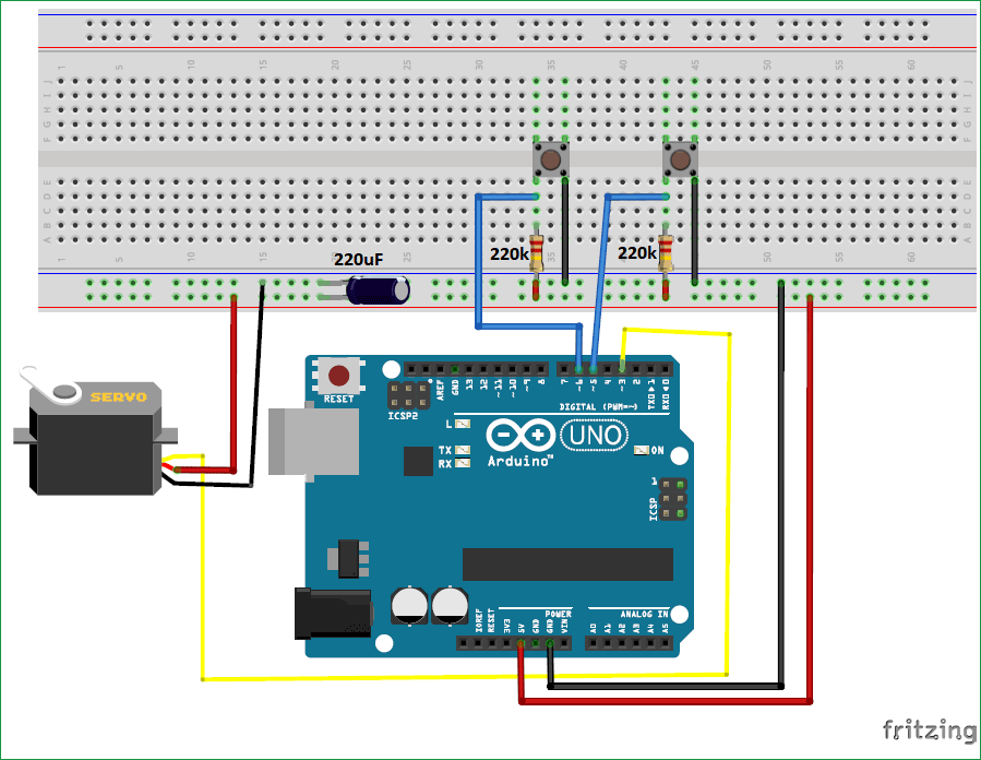
Usually, they have a servo arm that can turn 180 degrees. However, larger servos might draw more current which can reset the arduino.
New Servo Wiring Diagram Arduino diagram diagramtemplate diagramsample Arduino, Arduino

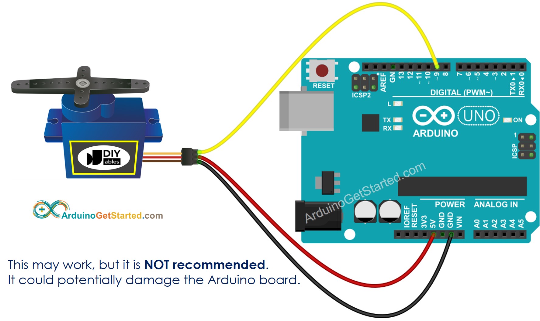
Servo motors have three wires:
Servo wiring diagram arduino. Writes a value to the servo, controlling the shaft accordingly. Servo motor arduino wiring schematics and source code for the more current arduino and robotio nano diagrams and information check out our robot servo controllers page. When the button is pushed, the servos will move to the open or up position and the led (eyes) will turn off.
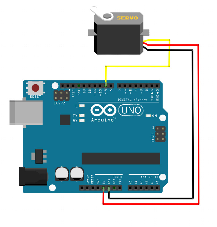
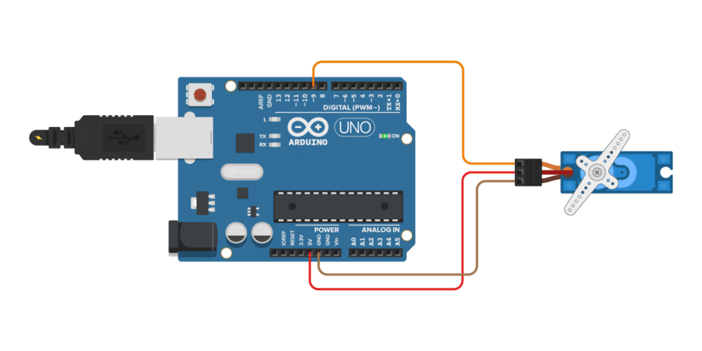
The servo motor has three leads, with one more than a dc motor. To build this example, you'll need the following materials. And finally, connect the orange wire from the sg90 servo to a digital pin (pin 9) on the arduino.
Mg996r servo motor wiring diagram click the image to enlarge it the mg996r is a metal gear servo motor with a maximum stall torque of 11 kg cm. Because with just a button we can actually rotate things like a knob mechanical regulator etc. Watch the above video and look at the wiring diagrams below to see how easy it is to connect your robots servo motors to the robotio board and start recording motion files with mecon.
Get your robotic arm making moves with the robotio nano arduino compatible brain board and mecon control software. Simply connect the power supply as shown in the wiring diagram below. Arduino servo tester wiring diagram.
They are very useful when you need precise position control and/or high torque. The power wire is typically red, and should be connected to the 5v pin on the arduino board. The servo tester moves the servo to zero degrees, waits 10 seconds, then moves to 90 degrees, waits 10.
Connect to the motor to the arduino as shown in the table below: You can also use this setup if your servo motor requires a different voltage than the arduino can provide e.g. Ad experienced repair service since 1985.
Servo motors have three wires. Schematics for emphasis, the connection is further described below. But sometimes we have to test that our servo motor is working well or not.
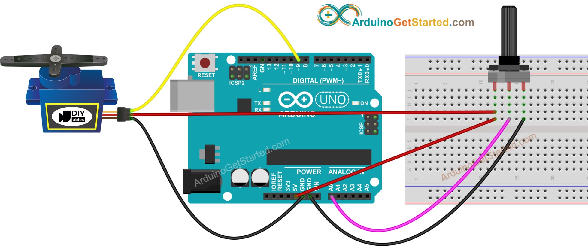
Using this circuit diagram you can interface a servo motor with an arduino board and control the position with a knobe arduino arduino projects servo arduino. The servo library supports up to 12 motors on most arduino boards and 48 on the arduino mega. This circuit is designed to give pwm pulse width modulation signal output by using this different duty cycle pwm pulse we can control the servo motor rotation and position.
The wemos d1 mini connects to the servo motor as. Wiring diagram the best thing about a servo motor is that it can be connected directly to an arduino. This pulsing signal tells the servo motor when to start rotating and which way to rotate.
The sg90 servo motor was chosen primarily because of its lower power consumption. On a standard servo, this will set the angle of the shaft (in degrees), moving the shaft to that orientation. Connect the red wire from the servo to the +5v on the arduino.
Most components can be found on amazon or aliexpress. Servo motors are great devices that can turn to a specified position. This project is a beginners tutorial on how to use servos.
I haven’t tried a larger servo motor but i presume using it, with the wemos d1 on wifi, will strain the device. My mg996r draws 10 ma at idle, 170 ma when operating but without any load connected and stalls at 1400 ma (!). The schematic diagram of servo system for ac two phase induction motor is shown in the figure below.
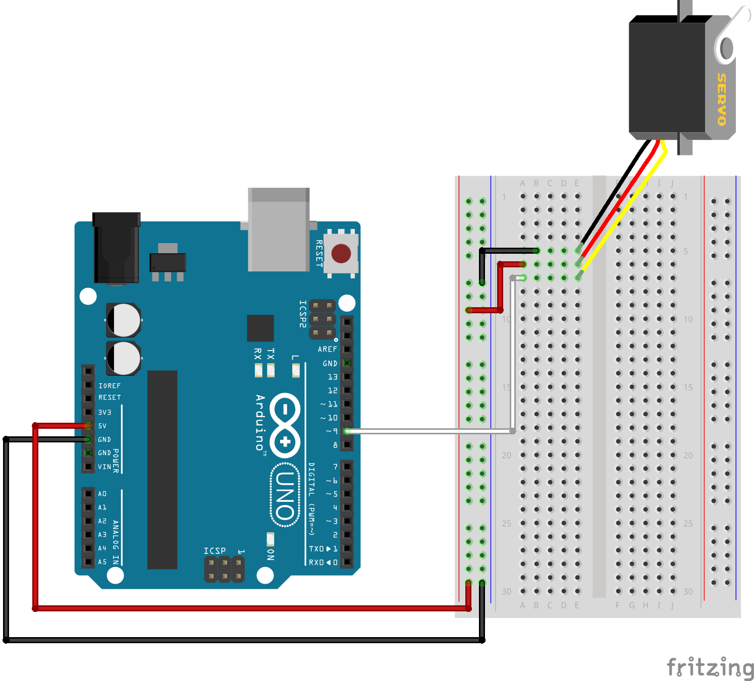
So that's why we always use arduino with servo motor. Servo driver circuit schematic simple circuit electronics circuit electronics. The ground wire is typically black or brown and should be connected to a ground pin on the arduino board.
Arduino to servo motor wiring diagram to begin, wire this circuit: Most servo motors run on 5v so you can attach the red lead to the arduino’s +5v pin. I will presume that you already know how a servo motor works with a microcontroller.
A wiring diagram is a kind of schematic which makes use of abstract photographic symbols to reveal all the interconnections of components in a system. A wiring diagram is a type of schematic. And finally connect the orange wire from the sg90 servo to a digital pin pin 9 on the arduino.
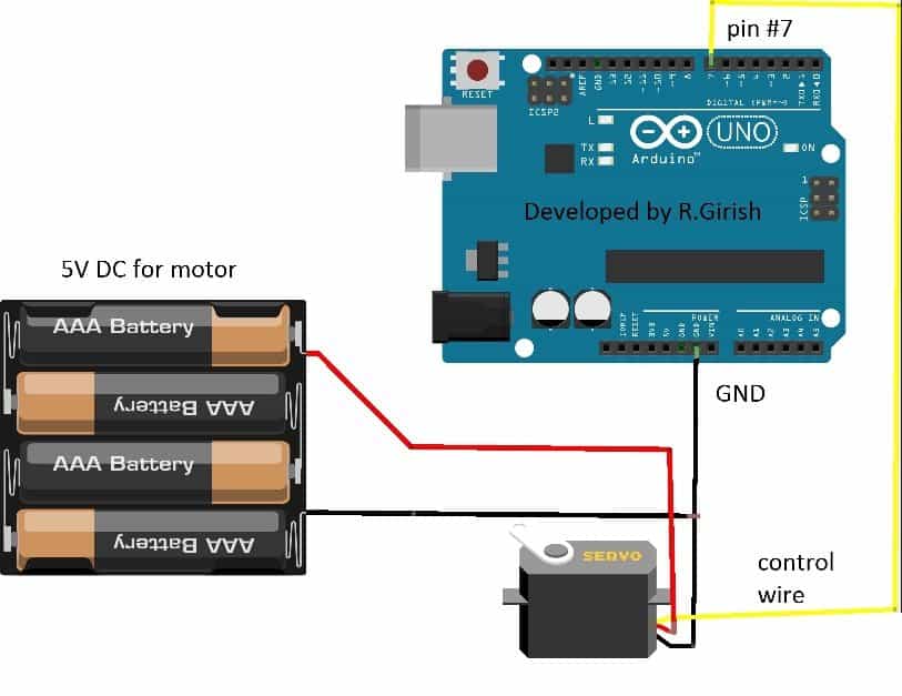
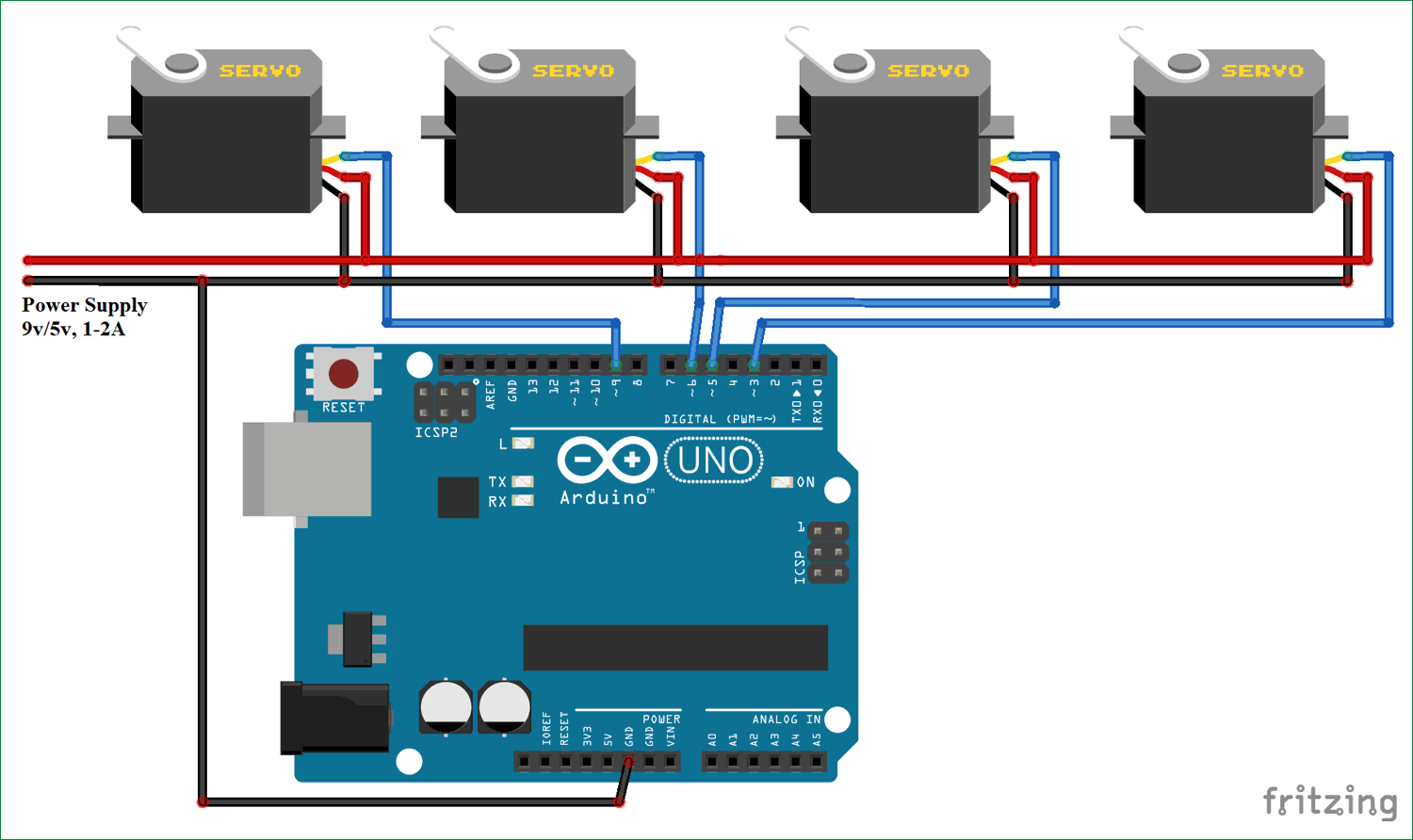
Servo motor powered with an external power supply. I have put together four cool projects for beginners. Drive 10 servos with 2 arduino pins wiring diagram google search arduino diagram 10 things.
In the rst part of this article, we will look at the inner workings of a servo and what type All you need is an arduino uno and a micro servo (i recommend tower pro 9g micro servos). Because they move on command, servo motors are an easy way to add motion to any project.
Connect the servo to the arduino as shown in the schematics below. Each lead has a color code. Often used in robotics projects but you can also nd them in rc cars, planes, etc.
I have included wiring diagrams and several example codes! New servo wiring diagram arduino diagram diagramtemplate diagramsample Using the arduino, we can tell a servo to go to a specified position and it will go there.
So you have to connect the brown wire from the micro servo to the gnd pin on the arduino. Make sure to connect the gnd pin of the arduino and the power supply together. Servo motor is a very useful device that only works when a square wave signal you can generate square wave signal by using 555 timer ic but it doesn't give the stable signal.
The first project is a servo tester. Controlling a servo with arduino. Learn how to use servo motor with arduino, how servo motor works, how to connect servo motor to arduino, how to code for servo motor, how to program arduino step by step.
Find this and other arduino tutorials on.
ArmUno MeArm Arduino Servo Wire Schematic
How to Interface Servo motors with Arduino
New Servo Wiring Diagram Arduino diagram diagramtemplate diagramsample Check more at https

Drive 10 Servos with 2 Arduino Pins wiring diagram Google Search Arduino, Diagram, 10 things

Connecting a Servo Motor to An Arduino Microcontroller Tutorials
Arduino Servo Resources Drake Principles of Technology

Create an Object Tracking System Part 2 Controlling a Servo Projects

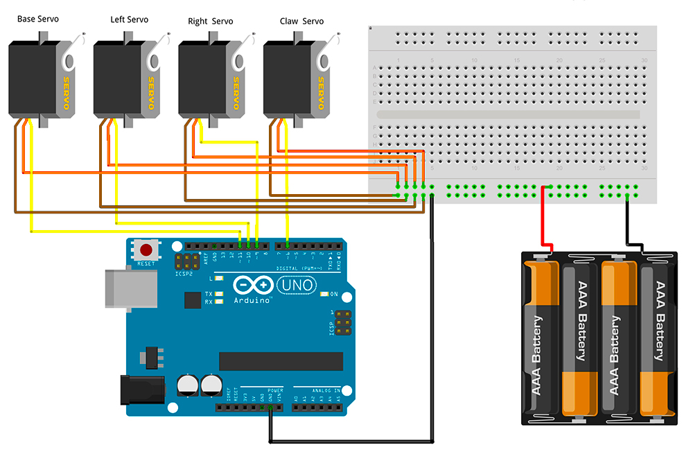
Controlling Multiple Servo Motors with Arduino
New Servo Wiring Diagram Arduino diagram diagramtemplate diagramsample Check more at https

How to Control Servo Motors with Arduino (3 Examples)
Servo motor control using potentiometer Arduino UNO circuit diagram in 2020 Arduino, Circuit

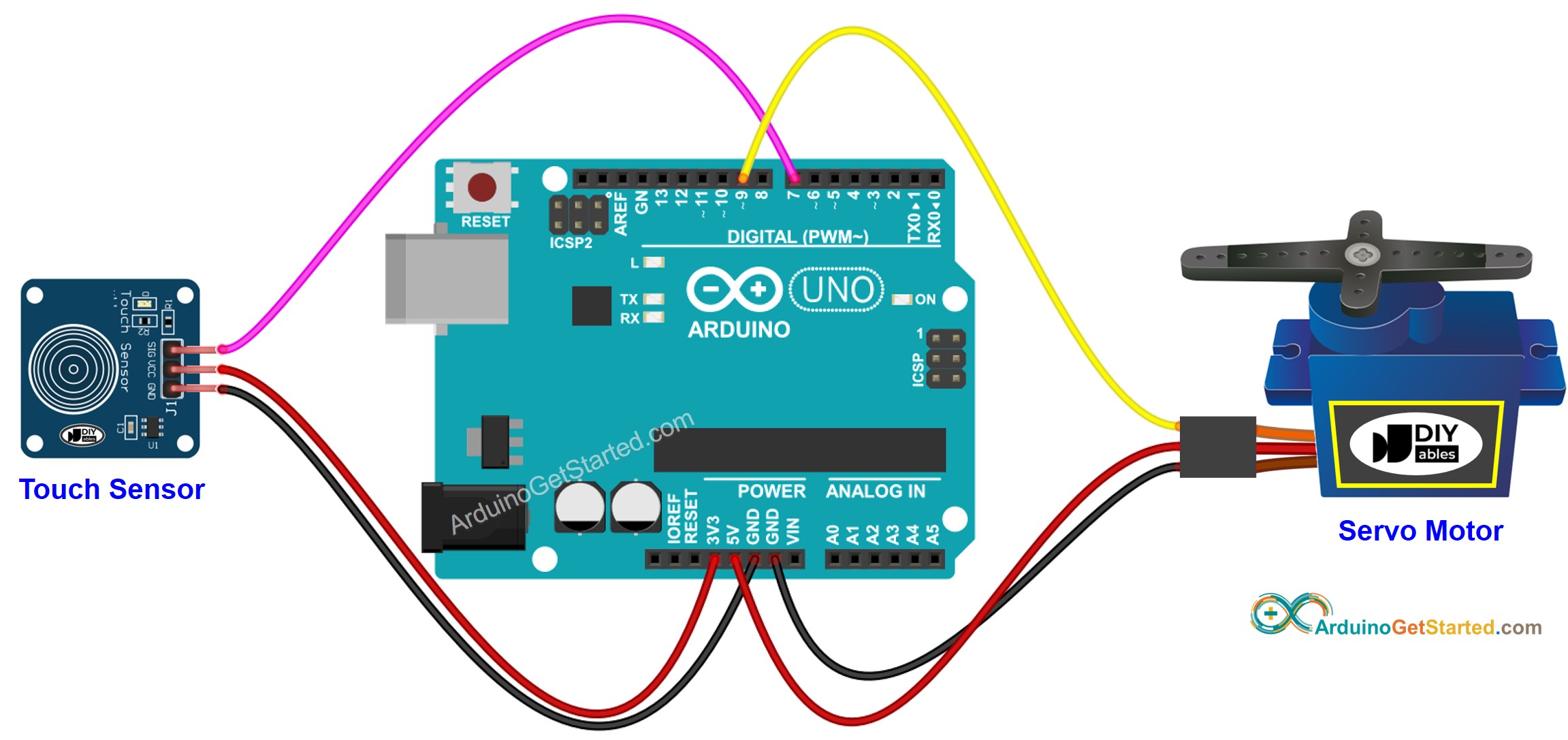
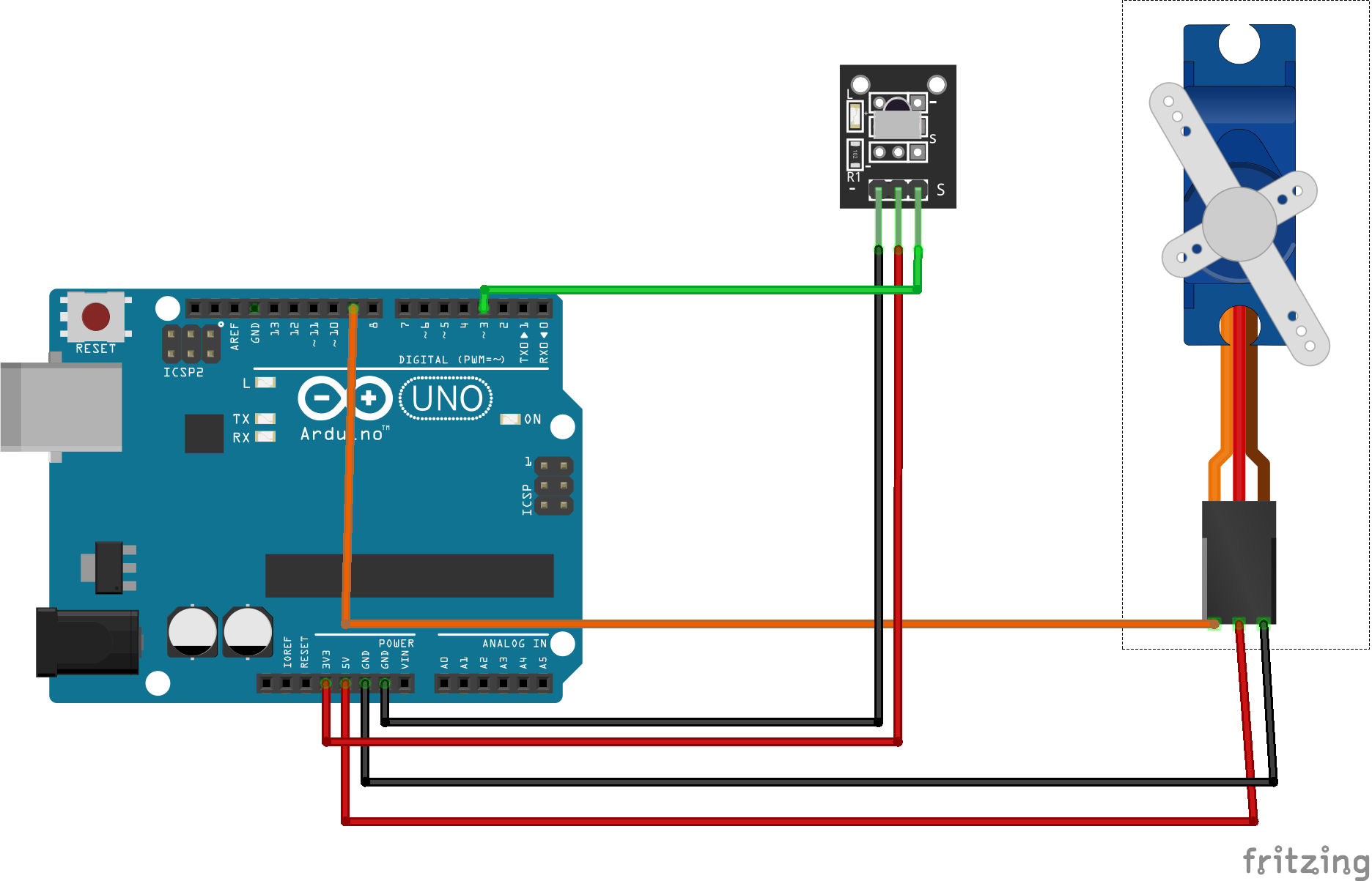
Arduino Touch Sensor Servo Motor Arduino Tutorial
Wiring Diagram Multiple Servos Arduino Meag
SIK Experiment Guide for Arduino V3.2
Arduino Servo.write() Référence du Langage Arduino en Français
Arduino Servo Motor controlled by Potentiometer Arduino Tutorial
servo motor control using arduino circuit diagram
Arduino lesson Controlling Servo Motor with IR Remote «
Parallax Continuous Rotation Servo Arduino, Arduino projects
