Restricted Earth Fault Relay Wiring Diagram
The 5b3 relay uses a low pass filter circuit to achieve this. During internal fault conditions, the relay and metrosil current and the magnetizing current of all connected current transformers is supplied from the fault current.
(PDF) A Novel Solution to Restricted Earth Fault Low Impedance Relay Maloperation

Ground fault relay wiring diagram.
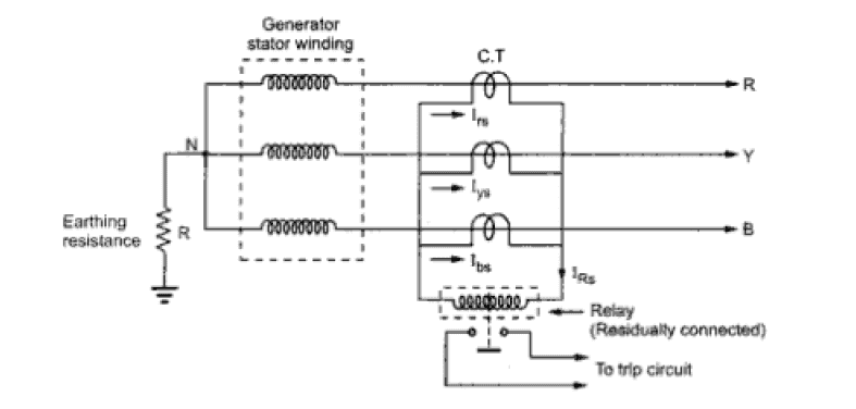
Restricted earth fault relay wiring diagram. The primary operating current is given by: Restricted earth fault operation under normal conditions and by application of kirchhoff’s laws the sum of currents in both current transformers (cts) equals zero. Alstom restricted earth fault cag14af14a,cag14af14a, alstom restricted earth fault cag14af14a.
The unbalanced currents due to single phasing or unequal loading on three phases, will flow only through the neutral path whereas, in the case of ground faults the fault current flows through the grounding path. Client has requested us to wire based on the wiring diagram below. Their most common application offshore.
Strong ground output relay wiring diagram converting polarity with spdt relays how to guides applications heavy duty 12 awg tinned copper wires autoswitch basics for the novice case use and why understanding automotive 5 pin socket harness mgi question when creating electric fan light. 2015 company fax:+91 80 26761720 Connection scheme the flexibility of ref 542plus allows the relay to be connected to the current transformers in different ways.
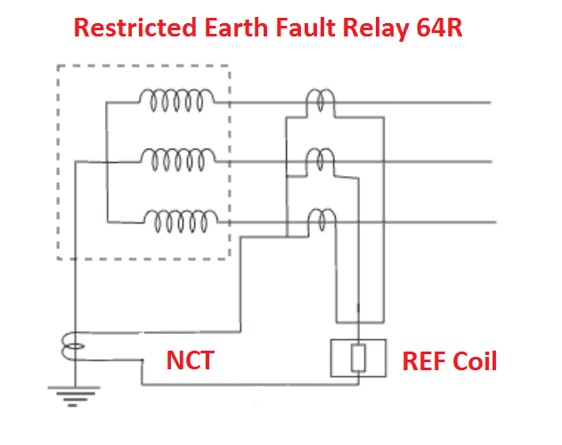
Wiring diagram digital microprocessor based restricted earth fault relay restricted earth fault relay (refr) an iso 9001 : Wiring backup cooling fan switch from ecu xweb forums v3. The illustration shows the principal of ref protection.
I have an application whereby the client is requesting for restricted earth fault protection and standby earth fault protection for transformer. Restricted earth fault relay (refr) protective relays and their introduction into the market. Improvement in protection is obtained in two ways:
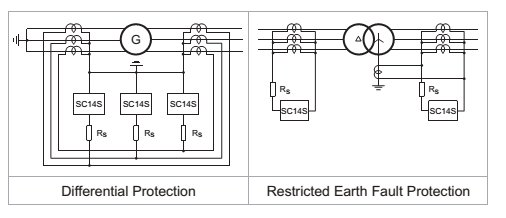
The ct secondaries ( phase and neutral cts) are wired to cancel each other’s currents during external faults and to drive all secondary current to the relay when the fault is inside the protected zone. Ground fault protection of any system depends upon the number of wires. An external fault in the star side will result in current flowing in the line current transformer of the affected phase and at the same time a balancing current flows in the neutral current transformer, hence the resultant current in the relay is therefore zero.so this ref relay will not be actuated for external earth fault.
An example of a real ref relay is included. The windings of many medium and small sized transformers are protected by restricted earth fault (ref) systems. For some restricted earth fault applications the primary fault setting needs to be greater at harmonic frequencies than the setting at the fundamental frequency.
The course consists of 19 lessons in 3h 14 min. Click to download catalog for cag14. Wiring a four poles rcbo or gfci circuit breaker three phase rccb wiring the three phase wiring for gfci or rcd rccb or rcbo wiring diagram shows the three lines l1 l2 and l3 and neutral has been connected as input to the rccb from main board followed by mcb ie.
No adverse reduction in fault setting can occur with the high frequency current, which may be produced during switching. Click to download wiring daigram for cag14. Overcurrent relays are also used on larger transformers provided with standard circuit breaker control.
Restricted earth fault protection of transformer. Iop = n (ir + nim) where ir = relay operating current and metrosil current at setting voltage, as given in the table below There is a difference between normal unbalance and ground fault currents.
The recommended relay current setting for restricted earth fault protection is usually determined by the minimum fault current available for operation of the relay and whenever possible it should not be greater than 30% of the minimum fault level. The area of protection is. But i have some doubts on their wiring diagram.
Cut out dimension (in mm.). Learn in detail restricted earth fault (ref) protection and its installation, connections & schematics (for transformer, motor, generator, shunt reactor and autotransformer), calculations and protection requirements. Click to download for wiring diagram cag14.
Earth fault protection in a solidly (effectively) earthed high voltage power systems EEP
Transformer protection differential & restricted earth fault EEP
Idmt Earth Fault Relay Wiring Diagram The Earth Images
[DIAGRAM] Wiring Diagram Of Earth Fault Relay FULL Version HD Quality Fault Relay EWIRENY

What is the difference between earth fault relay and restricted earth fault relay? Quora
Restricted Earth Fault

Earth fault protection in a solidly (effectively) earthed high voltage power systems Newsroom

High Impedance Restricted Earth Fault Protection [64H] Protection

[DIAGRAM] Wiring Diagram Of Earth Fault Relay FULL Version HD Quality Fault Relay EWIRENY
Restricted Earth Fault Protection Philosophy ELECTRICAL TECHNOLOGY AND INDUSTRIAL PRACTICE

Difference Between Restricted And Unrestricted Earth Fault Protection The Earth Images
Page not found University Housing & Dining Services Oregon State University

Power transformer protection relaying (overcurrent, restricted earth fault & differential) EEP
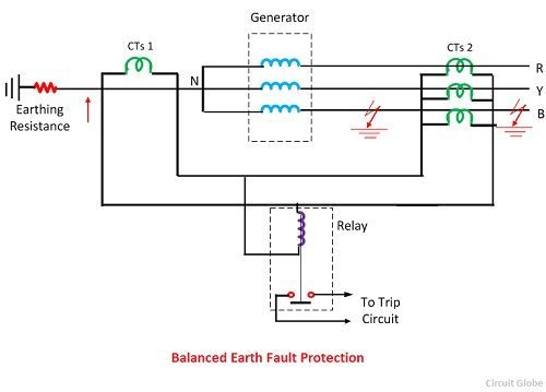
Balanced Earth Fault Protection of a Generator Working, Connection & Drawback of Earth Fault
SC14S Instantaneous Earth Fault Relay Electrical & Automation L&T India
Restricted Earth Fault Protection your electrical home

[DIAGRAM] Wiring Diagram Of Earth Fault Relay FULL Version HD Quality Fault Relay EWIRENY

Ground Fault ProtectionRestricted versus Unrestricted Methods

Earth Fault Relay Wiring Diagram Wiring Diagram